Oil Pipeline Quiliano-trecate 8”
The oil pipeline Trecate-Quiliano, DN 8” (200 mm), belonging to Sarpom s.r.l., crossed river Bormida di Spigno hung to the existing railway bridge, in the territory of Mombaldone Municipality (Asti province, North Italy).

 13.06.2014
INTRODUCTION
The oil pipeline Trecate-Quiliano, DN 8” (200 mm), belonging to Sarpom s.r.l., crossed river Bormida di Spigno hung to the existing railway bridge, in the territory of Mombaldone Municipality (Asti province, North Italy).
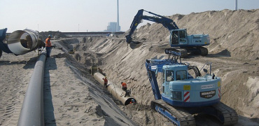
In order to eliminate that aerial crossing and locate the pipeline under the river bed at a depth sufficiently safe regarding the river dynamic evolution, a route bypass of the river crossing was carried out on March 2014 adopting the trenchless technology known as Horizontal Directional Drilling (HDD).
The design of such a intervention was based on the results of the subsoil investigation performed on behalf of the Client, which pointed out the stratigraphical subsoil situation consisting of a marny rock substratum covered by coarse fluvial alluvium with sand, gravel and cobbles.

Aerial view of the area, HDD route yellow line (by Google Earth)
SUBSOIL CHARACTERISTICS
The subsoil stratigraphical situation, as resulted from the geotechnical investigation and as actually ascertained during HDD drilling, can be summarized like the following:
1) Fluvial deposits at the entry side
- Sand and silt, thickness around 3-4 m
- Gravel and cobbles with silty-sandy matrix, up to the top of the rocky substratum, at a depth of 7.50-8.00 m.
2) Rocky substratum
- Compact marl, at times limestone marl, horizontally stratified. At the top a 20-30 cm thick layer of weathered marl is present. Such a substratum was encountered at the HDD entry point at 7.50-8.00 m, while at the exit point it is covered by 3-4 m thick eluvial-colluvial deposits.
3) Eluvial-colluvial deposit at the exit side
- Such a soil is present at the base of the hill next to the HDD exit point, and mainly consists of silt and sand covering the marly substratum with a thickness of 3-4 m.

Schematic geological section along the HDD profile
HDD PROFILE
The HDD profile was defined on the base of the subsoil characteristics, of the geometric and elasticity parameters of the pipe to be installed and of the local constrains. In particular:
- due to the presence of very coarse material in the cover layer (7.50-8 m thick) a steel protective casing pipe had to be installed for all the length of crossing such a cover soil. In the same time a entry angle of 12° was adopted in order to keep the length of the casing within adequate limits for a easy installation (50 m).
- The profile had to guarantee a safe depth under the river bed, even in case of the water course hydraulic evolution.
- A slight horizontal bending had to be adopted (R= 1000 m) in order to have the final straight section of the profile aligned with pipe string (prepared in two sections) which could not be differently located due to local constrains.
- A exit angle of 12° was defined to keep a low height of the pipe overbend at the exit point.
- Adopting a vertical radius of 440 m and a horizontal of 1000 m, the resulting combined radius was 400 m, value that is the minimum consistent with mud motor use and in the same time adequate to the geometric and mechanical characteristics of the pipe.
Using as geometric parameters: entry angle= 12°, exit angle= 12°, vertical radius= 440 m and horizontal radius= 1000 m, the following schematic profile was defined.

Schematic HDD profile
DRILLING CHARACTERISTICS
The HDD profile, defined in the final design on the base of the above listed items, consists of a straight entry section, a bending section, a straight exit section, as below specified.
| GEOMETRIC DATA | |
| Entry angle | 12° |
| Exit angle | 12° |
| Straight entry section length | 42.63 m |
| Bending section length | 182.96 m |
Straight exit section length | 96.78 m |
| Vertical bending radius | 440 m |
| Horizontal bending radius | 1000 m |
| Combined radius | 404 m |
| Drilling horizontal length | 322.37 m |
| Drilling real length | 328.17 m |
Exit point elevation was 11.5 m higher than the entry one. LMR used for this HDD the Rig 80/50, with 1000 kN pull/push force and 55 kNm torque.

Rig 80/50 with 1000 kN pull/push force
5” drilling rods with a drilling 12.25” tricone bit and a 8” mud motor were used.

BHA (bottom hole assembly) with 12.25” drilling bit
The first section, crossing gravelly layer, was reamed with a hole opener up to 18” and then a 13” 3/8 casing pipe was installed for a length of 50 m, entering around 5 m the rock substratum.

18” hole opener

13” 3/8 casing installation
DRILLING PHASES
The drilling activity, up to the final installation of the product pipe, comprised the above listed activities.
- Pilot drilling through all the cover soil extension up to entering for an adequate length into the rock substratum.
- Trip back of the drilling pipes, disconnection and installation of the 18” hole opener.
- Reaming of the pilot hole up to 5 m inside the rock.
- Trip back of the pipes and disassembling of the hole opener.
- Installation in the enlarged hole of the casing pipe for a total length of 45 m, of which 4 in the rock.
- Restarting of the pilot drilling for the remaining section, as long as punch out precisely at the exit point, at a horizontal distance of 322 m.
- Pull back of the preassembled pipe string in two sections. During the break due to the connection of the two pipe sections, the casing at the rig side was pulled out.
The timing of the above listed activities was:
- 25th March: 12.25” pilot drilling up 57 m
- 26th March: pilot drilling up to 124 m, trip out 6 joints, 18” HO assembling and hole reaming up to 45 m
- 27th March: trip out the drill pipes up to disassembling the HO, installation of the 13” 3/8 casing pipe up to 45 m (4 m below the soil cover-rock contact)
- 28th-29th March: pilot hole completing and precisely punching out at the exit point
- 30th March: pull back of the 8” pipeline with a break of around 3.5 hours for connection of the 2 string sections and for pulling out the casing at entry side.
 |  | |
| Punch out at the exact location! | String corridor with the two preassembled pipe sections |
FINAL CONSIDERATIONS
The activities for drilling the hole and installing the 8” pipeline under the bed of the river Bormida at Mombaldone were successfully carried out in the range of 6 days, from 25th March to 30th March. The drilling reached with high precision the exit target and the pipeline was easily and without any damage installed in the hole.
The main expected difficulties were the crossing, at the entry side, of the cover layer with loose and very coarse soils (gravel and cobbles) 8 m thick, which could have caused serious problems for the hole stability and for the drilling progress.
The solution LMR adopted, that is the installation of a protective casing pipe by means of the rig itself, resulted absolutely functional and allowed the drill progress and the pull back of the product pipe without any difficulties regarding hole collapsing and obstruction.
The drilling progress in the marly rock section (around 75% of the whole length) was carried out, even if with adequate slow speed (20-25 min/joint), without any particular problems thanks to the proper choice of the drilling bit and of mud composition.
At this regard it has to be noted that marly rock, rich of clayey minerals, when crushed by drilling action enhanced fine particles accumulation in the drilling mud which could not be separated by the recycling unit causing increase of the mud unit weight. For this reason mud had to be more times dumped and replaced with fresh one.
Mud pressure in the hole during drilling (see following graph) reached a maximum value of 300 kPa. No mud loss or inadvertent return to surface occurred, thank to rock compact structure without fractures and joints.
Drill push force and torque during drilling were low, of the order of 100-130 kN and 6-8 kNm respectively. Also in the pull back phase the applied pull force was moderate, not exceeding 60 kN.

Main parameters graph as recorded during drilling
Contact

LUDWIG FREYTAG GmbH & Co. Kommanditgesellschaft
Ammerländer Heerstr. 368
26129 Oldenburg
Download vCard
Phone +49 441 9704-0
Fax +49 441 9704-100
info@ludwig-freytag.de
Company group
The right partner for every project
At Ludwig Freytag, you will benefit from the entire expertise of a renowned company with over 130 years of experience and the wide variety of services from a strong group of fourteen individual independent companies. Take advantage!
Careers
Get the Freytag feeling
Great group, great appreciation, great opportunities: each member of the Ludwig Freytag Group offers you excellent perspectives. See for yourself!